Tuesday, October 29, 2019

PART 6 - Hacking the remote codes - DIY Infrared receiver for Pioneer Tapedecks

If you haven't read Part 5 - start here!

Hacking the remote codes


The Arduino IR Lib IRremote.h comes in very handy when you want to read the commands send from you remote.

You can use the same parts i used to create a IR receiver to build you own hacking tool.

The IRremote library comes with a sample Program that does the exact same thing that my small IR snooping program does.

Snooping program.

#include <IRremote.h>
int RECV_PIN = 11;
String stringOne = "";
IRrecv irrecv(RECV_PIN);
decode_results results;
void setup()
{
  Serial.begin(9600);
  irrecv.enableIRIn();
}
void loop()
{
  if (irrecv.decode(&results))
  {
    Serial.println(results.value, HEX);
    irrecv.resume();
  }
}


Black goes out of the image to pin 11.


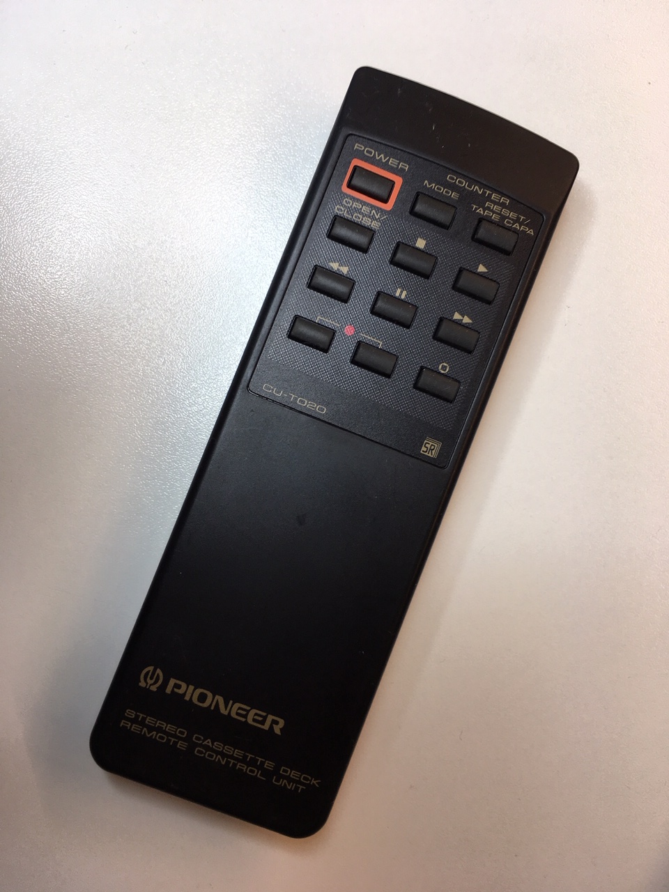
I took the original Pioneer remote control and pushed all buttons to see what comes out.

Out comes a 32 bit hex number. For example: 0x85ae817 when play is pressed.

The results of the Snooping Program

Button Pressed Header (HEX) Payload (HEX)
Power0x857a0x38c7
Mode0x857a0xE21d
Reset / Tape Capacity0x857a0x12Ed
Open / Close0x857a0x4ab5
Stop0x857a0x6897
Play0x857a0xe817
Rewind0x857a0x8877
Pause0x857a0x18e7
Fast Forward0x857a0x08f7
Record (two buttons)0x857a0x28d7
Rec Mute0x857a0x48b7


As you can see the header is always the same, Two Bytes indicating that this is for a Pioneer tape deck. Hex 0x857a.

The next Two byte is the Payload or the actual command.

In a brute force scenario this leaves out Hex 0xffff, minus the 11 codes i already know, in human numbers - 65524 possible codes to run through.

Brute force is very time consuming, but maybe there is a system to the commands.

For example the Play and Pause buttons are very similar. 0xe817 and 0x18e7. The first 4 bit (e) has swapped place with the first 4 bit of the next byte. Even Stop is similar, it has 8 and 7 in it - 0x6897

For those playing along a home - 4 bit is called a nibble. Another fun fact, Pioneer uses NEC IR command Protocol, which are based around 4 bit cpu's.

Rewind is 0x8877 and Fast Forward is 0x08F7. Again something happened to the first nibble of each byte.

Looking at all the commands it is obvious that the 8 and 7 are in most common commands. Like Play, Pause and so on. Fixing 8 and 7 into a mask like this 0x_8_7 leaves 256 minus 8 commands to brute force through.

But there is more, if you look at the Payload codes in 4 bit binary, like the Play Button, it looks like this.

0xe817 = 1110 (e) 1000 (8) 0001 (1) and 0111 (7)

Command-set is red - command is green.

1000 (8) and 0111 (7) are complementary nibbles - they always adds up to 16, but so are the two other pairs 1110 (E) and 0001 (1) - and if you look at all the commands, they are all complementary.

The whole thing is setup in 16 sets of commands.

In the above scanning program i found 3 Command-sets: 0x_8_7, 0x_2_D and 0x_A_5. But there are more sets beginning at 0x_0_F going to  0x_F_0. A command set like 0x_0_E is not valid because 0 and E aren't complementary, but 0x_1_E is valid. So we have 16 sets of commands.

And the commands within the command-sets have 16 valid commands. 16 times 16 equals 256 commands in total. One could say it's a waste of possible commands you could have 65535, but hey - room for 256 is more than enough in this world for a Tape recorder.

To brute force this is a piece of cake. 🎂

My old Arduino grinding through all 256 Commands

I ran all 256 codes (twice) and found 3 new code: 😁


  • Monitor button - 0xb847
  • Meter Mode - 0xf20d
    • (changing meter from normal to top level, then to bias level and then back again)
  • Return to Zero  - 0x728d
    • (which rewinds the cassette to 0000 or the beginning of the tape, whatever comes first)
As you can see those are unfortunately all in two of the knows Command-sets. The 0x_8_7 and the 0x_2_d. All of the other sets turned up blank. 

Of the three new codes the most practical is, in my opinion, the Monitor button.

Here is my Brute-Force Program, which isn't so brute:


#include <IRremote.h>

IRsend irsend;

long pioneerCassette = 0x857A0000;
long knownCodes[] = { 0x38C7, 0xE21D, 0x12ED, 0x4AB5, 0x6897, 0xE817, 0x8877, 0xE817 , 0x08F7, 0x28D7, 0x48B7 };

void setup()
{
   Serial.begin(9600);  
}

void loop() {
  long testCode = 0x0;

  for (int bc = 0; bc < 16; bc++) // Counting command sets  
  {
    unsigned int bch = bc << 8;
    byte bcl = ~bc - 0xf0; 

    baseCode = pioneerCassette + bch + bcl;

    for (int c = 0; c < 16; c++) // Counting commands
    {
      unsigned int ch = c << 12;
      byte cl = (~c - 0xf0) << 4; 

      testCode = baseCode + ch + cl;
      if (!isKnownCode(testCode)) 
      {
        Serial.print("SENDING:");  
        Serial.println(monitorCode,  HEX);  
  
      for (int i = 0; i < 3; i++) {
      irsend.sendNEC(testCode, 32);
      delay(40);
      }
  
        while(Serial.available() < 1)
        {
          // read anything serial input
          // press enter sends the next command
        }
        while(Serial.available() > 0)
        {
          // clear read buffer with a dummy read
          byte dummyread = Serial.read();
        }
      delay(500); // half a second delay between each command
      }
      else
      {
        Serial.print("IGNORING:");  
        Serial.println(testCode,  HEX);  
      }
    }
  }
}

boolean isKnownCode(long code)
{
  int arraySize = sizeof (knownCodes) / sizeof(long);
  for (int x = 0; x < arraySize; x++)
  {
    if ((pioneerCassette + knownCodes[x]) == code)
    {
      return true;
    }    
  }
  return false;
}


Hope this helps you hunting codes for your device.

Cheers 🍻
Per


Monday, October 28, 2019

PART 5 - The original remote - DIY Infrared receiver for Pioneer Tapedecks

If you haven't read Part 4 - start here!

The original remote


As you might remember from Part 2, the Logitech Library doesn't have the Mode, Reset / Tape Capacity, Record Mute or the Open / Close buttons available.

So i started a search on Ebay and found this Original Pioneer CU-T020 Remote Control Unit.

Pioneer CU-T020

I don't know from which unit this came, as i wrote earlier - none of the European CT-S Tape deck could be remote controlled directly, you always needed a Receiver or an Amplifier - and those did have remotes, with basic tape buttons.

Maybe - just maybe - you could order an extra remote to your CT-S to get these extra button, otherwise i guess these remotes are from the Japanese models, like the T-1100S.

The remote works perfectly with my little Tapehack. I was eager to program these missing buttons into to the Logitech Harmony 650.


It wasn't an easy task, i can tell you. Countless times to tried to record just a single command like the Reset / Tape Capacity. Every time the Harmony 650 recorded the same button multiple times - even a short push of the button produced the same button 2 or 3 times.

This is not an issue with say the Play button. When the Tape deck goes into play mode additional play commands are simply ignored.

Me pressing the Mode button - again and again. The IR Receiver in Harmony 650 is in the back.

The Mode and Reset / Tape Capacity are both switching buttons, they cycle through 3 modes (Tape counter, Tape time and Remaining Time) and when in Remaining Time mode, it has 4 Tape Capacities to choose from (C46L, C60, C80L, C90) - So pushing one button on the Harmony 650 could cycle though all modes, which is very annoying.

However the MyHarmony Software lets you configure how many times the Harmony 650 will repeat the Remote commands. I selected to lowest - Zero. This setting didn't change anything at first.

Then i found out, instead of re-recording the Command, if i deleted the button first and the added it again with the exact same name, it was more likely to be recorded correctly.

After some back and forth - its working fine, just like the original.

Now i have a fully functional copy of the Original Remote, but it made me curious - could there be more commands available for the remote? Like Dolby On / Off or Dolby B, C and S?

There is a nice IR Library for the Arduino board. I will try to make a test board that cycles through all of Pioneer Tape deck commands - there might be more functions available. (😱 - OMG. i just realized that there might be 1000's of IR Codes to cycle through)

It is not something i know for sure, but some years ago i found a remote IR command for Sony DAT recorders which turned the service mode on, the whole VFD display turned on, and another push showed how many hours the DAT head had been running.

Cheers 🍺
Per


Saturday, October 19, 2019

PART 4 - The soldering - DIY Infrared receiver for Pioneer Tapedecks

If you haven't read Part 3 - start here!


The soldering

As i showed in part 3 i found this old serial IR receiver, i believe i bought it in 1998 for my first DVD PC Player software.


Serial PC IR Receiver


I went to the electronic part store and bought a Stripboard, you can use them for prototyping or like me for small hacks.

Stripboard.
As you can clearly see, it is too large to fit in to the small remote box. So i used the original board as a template.

Find a spot where it fits.


Here you can see the outline of the original board.
Get you saw and cut it along the outline to create you own board from the Stripboard.

The cut-out in the box - fits!
It is not a "perfect" fit, but it will do. Next, solder all the components to the mini Stripboard. For that i need some wires.
  1. The Mono Trigger cable. 
  2. The Ground cable to provide a common ground between the Remote receiver and the tapedeck.
  3. And a suitable USB 2.0 or 1.0 cable to provide the Power +5V for the Remote receiver.


Mono Trigger cable and below the Ground cable.
To get the idea, here how this will be connected when its done. 


Cut all 3 cables to the same length, make the ground cable a bit longer so that you have some slack, when screwing it to the tapedeck later.

I'll jump right to the finished part. Oh, my god, i soldered the components on the wrong side! 😱

Up in the left corner the Red and Black wires from the USB cable provides +5 Volt and Ground. The trigger cable is connected directly to the Out of the IR Receiver. And behind going off to the left is the much thinner ground cable.

Alternatively you could use a minijack Stereo cable instead, this way you would only have two cables out of the Receiver box. The Trigger signal must go the the Left channel (white wire) and the Right channel (red wire) goes to ground. On the receiving end you must then breakout the red wire and connect to the chassis of the tapedeck, because the Control IN connector doesn't provide Ground, as discussed in Part 1 of this Blog.

As you might see i have bend the pins of the IR Receiver in a S-Form because it is a relative big component. If i soldered it directly on the board it wouldn't have fit inside the box.

All soldered.

The other components were soldered on to the board just like on the breadboard. You can see that i mounted the both capacitors horizontally, so that they fit well inside the box.

This all depends on your box size.

Me trying to fit the 3 cables in a way that all gets out of the same hole!
I snapped the lid on and connected it the the Pioneer tapedeck.


Trigger cable goes to Control IN and the ground wire is screwed onto one of the screws on the backside.
So everything is hooked up - all i have to do now is to test the end result.

Roll video:


That's it! I am so happy with this solution.

The good thing about this hack is, you can use it with any of the Pioneer CT-S models that have a Control IN Port on the backside.

Here is small list:

CT-95, CT-43, CT-S900S, CT-S910S, CT-S920S, CT-S810, CT-S820S (obviously), CT-S830S, CT-S710, CT-S720, CT-S730S and on and on the list goes.


Hope you liked this DIY blog. Please write a comment if you did!

Cheers 🍺
Per

Go to Part 5


Wednesday, October 16, 2019

PART 3 - The control bus - DIY Infrared receiver for Pioneer Tapedecks

If you haven't read Part 2 - start here!


The Control Bus


Like a real bus bringing passengers from one station to the next and so forth, the control bus from Pioneer, called SR (System Remote), is bringing IR data (binaries) from  the Receiver or Amplifier to the tapedeck, if the binary data wasn't meant for the tapedeck, you can connect that to the next unit and that to next again. Every unit is listening for signals.

So you can daisy chain the units, Amp to Tapedeck, Tapedeck to CD player, CD Player to Tuner, etc. etc.

I found Adrian Kingstons great website, which in detail describes the Pioneer SR format.


From his website i learned the following about the control bus:

"This is simply a TTL +5V rail supplied by the receiving end (CONTROL IN). The sending end (CONTROL OUT) pulls this rail down to 0V (GND) with pulses that are the same as the NEC protocol described above except that the pulses are unmodulated, that is there is no 40kHz carrier inside each pulse, its just a solid period of 0V."

With the important note:

"Note that the tip pin of the CONTROL jack plug is the SR bus pin and the ground connection between the units needs to be made with an audio ground from the LINE IN/OUT connectors."

Lets boil that down to the following.

  • Must buy 40kHz IR Receiver.
  • I need +5 Volt and a common ground.
  • The output of the IR receiver must be +5 Volt.
  • Any signal coming out of the IR receiver must pull the +5 Volt down to 0V.
  • the CONTROL IN supplies +5 Volt ?? - really?

I found this TSOP31240 IR Receiver Module running a 40kHz in a range from +3V to +6V.

It's a good ideas to protect the IR Receiver against EOS (Electrical Over-stress) and in general to stabilize the Receiver with the following components. Sometimes IR Receiver are sold on a mini-board with these components already mounted and ready for user with an Arduino or other micro-controllers.


So this is what i came up with, i measured if ground comes out of the CONTROL OUT connector. And just like Adrian wrote on his website, ground is not connected at all.


Me, measuring ground to ground - no result.
I then measured if the IN or OUT provides +5V. Yeah, well OUT does provide +5V, but it's the data line which is always high +5V. To use the data line as power provider for the new IR Receiver is not a good idea. (trust me i tried)

So i am stuck with using an external power supply for my design.

Components line-up to test with the breadboard:

The usual suspects...

From left to right:

  • The IR receiver TSOP31240 (40kHz) Pins from left to right: 1. Ground, Vcc and Out
  • Electrolytic capacitor 10V 10µF 
  • Ceramic capacitor 0.1µF
  • Resistor 10k Ω (long legs)
  • Resistor 100 Ω (short legs)
(See also the Schematic Diagram above)

This is how i hooked the components up on the breadboard.

Breadboard with components seen from behind.

Please note that the electrolytic cap minus pin must go to ground. the black cable going off to the right is Out. No signal from remote and it is high (+5V), any signal should pull it to Ground.

As a power supply for this test i used an Arduino clone.

Mini-scope with breadboard.

I plugged the Mini-scope (5V per division) on Ground and Out, then pressed Tapedeck Play on the Logitech Remote control.

YES - ITS ALIVE!!

In Trigger mode you can see the Play Button IR codes as they are pulled down from +5V to Ground.

Lets plug it in the Pioneer CT-S820S CONTROL IN port.

I only had a stereo cinch to mini-jack cable, that's fine. Left channel (white) is the data line. For the real setup i will use a mono trigger cable as they are called.

Note the dodgy ground wire to in the upper left, clipped to one of the chassis screws. The Uno's role is power supply.

Roll video:


Sorry about the dishwasher noise in the background, meh! Thou shall have clean plates!

I am really surprised that it just worked like that. Really great news.


Next steps
  • Get some nice cables.
  • Solder them on board.
  • Throw it in a nice package.


I found this package from 1998, this will do fine. Old serial remote receiver box.


Go to Part 4.

Sunday, October 13, 2019

PART 2 - The remote - DIY Infrared receiver for Pioneer Tapedecks

If you haven't read Part 1 - start here!


The remote


Got this great remote-control some years ago, it is still available but check out the online price before buying, they vary a lot.

The Logitech Harmony 650.

Logitech Harmony 650

You can control up to 8 devices with the possibility to add extra buttons on the display.

With the software from Logitech, called MyHarmony, you must first select you remote.


Then you add a new device, in my case the Pioneer CT-S820S.


Now you can assign the buttons. Most are selected automatically.


It's a good idea to move the mouse over the selected buttons to see which buttons the software did select, i doesn't always make sense.

In general some features functions are missing, like:

  • Counter Reset
  • Counter Mode
  • Eject
  • Dolby on/off and select
  • Rec Mute
  • Display on/off
  • Meter mode
If i could find a remote for the Pioneer T1000S or the T1100S, these actually has Counter Mode, Reset and Rec Mute Buttons.

All i have to do now is to synchronize these setting to the Harmony 650 remote.


So the next step is to find out how to send IR data from the Logitech into the Pioneer through the control bus.

Time to research...


Go to Part 3.


PART 1- Pioneer CT-S820S - DIY Infrared receiver for Pioneer Tapedecks

Pioneer CT-S820S


So i just recently picked up this great Pioneer CT-S820S high-end Cassette Player.

According to hifiengine it was produced from 1993 to 1994 so that's about 25 years ago, at the end of the line for Compact Cassettes.

Pioneer CT-S820S - 25 years old
For at least 5 years i have been searching eBay and other marketplaces for a decent, affordable high-end cassettedeck. Off cause i have dreamed of Revox B215 or the Nakamichi Dragon or even the Sony TC-K 909ES, but with price-tags around 1000 to 2000 € that is way beyond my budget.

Then i discovered the Pioneer top player, the CT-95, which is also far from what i can afford, but its smaller brothers like CT-S920S or the CT-S820S are much more in my league.

Inside the Pioneer CT-S820S
But one thing is really annoying about these decks, almost all of them doesn't have a built-in IR receiver. When i disassembled and cleaned my CT-S820S i discovered that the right front control-board actually was laid out for remote controlling, but the electronic components are missing and even the silkscreen on the board is missing. So you can't really see what to put where.

On the outside
Front right - no Remote control window.

Inside
No components and no silkscreen.
On the silkscreen you can read the word "flat", but on the front it's actually "Super Auto BLE". Pioneer used this same board in several high-end models, here a small image from the Japanese T-1100S where you can see the IR cutout and the "flat" button.


The missing components is a solvable problem. but the real challenge is the metal front of the deck, it doesn't have a hole for the IR receiver - like the T-1100S above - and drilling a hole through the nice metal front would only destroy its value - and therefore not an option.

But there is another non destructive way.

On the backside of the tape deck there are two a remote-control link terminals. Which makes this tapedeck controllable from other Pioneer Amplifiers or Receivers.

The Control Bus
You simply connect these with a mono mini-jack cable, chaining them together through the in/out connectors and you should be good to go.

Then again, this is my only Pioneer equipment, so i can't use this simple option.

Who came up with this crazy idea anyway? Pioneer sales dept? For what reason? To force customers to buy Pioneer only? Pioneer still pursues this strange policy.

Oh, and then i need a remote-control (needless to say), but these tapedecks, without IR receivers, were sold without a dedicated remote-control. You'll need a System remote for Amps or receivers, which offered somewhat rudimentary tapedeck control buttons.

Luckily a have a Logitech Programmable Remote-control, which can learn from other remotes and already has a very comprehensive online library of codes to control almost any kind of IR units.

Even Pioneers CT-S820S is included, so it is just a question of downloading and configure the Logitech to remote control the Pioneer tapedeck.

Next steps:


  1. Configure the Logitech remote control.
  2. I need to find out how Pioneers SR remote control bus works
  3. Get the hardware (IR receiver)
  4. Build a mock-up on a breadboard
  5. Test it out.

Go to Part 2